INTERNAL WORKFLOW · SEPTEMBER 7, 2026
From a dragon GLB to a 100 mm STL
A real conversion example, with the geometry and slicer checks that come after the download. This is an Image3D internal demonstration, not a customer story or a physical print test.
Try the same conversion →By Image3D · Tested September 7, 2026
1. Start from an existing generated model
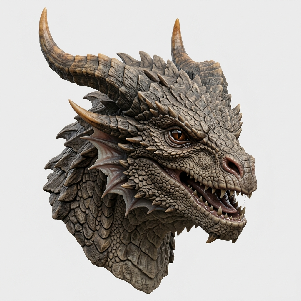
We reused the dragon model already available in the Image3D gallery. No new generation was needed for this workflow. The input is a textured GLB; the result below is a geometry-only STL.
2. Set the height and convert
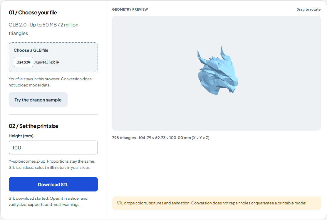
Open the converter and choose “Try the dragon sample.” Leave the height at 100 mm, rotate the preview and download the STL. The tool changes Y-up to Z-up, scales all mesh parts together and places the lowest point at Z = 0. It does not merge, repair or reconstruct the mesh.
3. Check the downloaded file
| Downloaded STL check | Observed result |
|---|---|
| Triangle count | 798 (unchanged) |
| Size, X × Y × Z | 104.79 × 69.73 × 100.00 mm |
| Open / degenerate edges or faces | 0 open edges / 0 degenerate triangles |
| Non-manifold edges | 7 — not repaired by conversion |
| Binary file size | 39,984 bytes |
An independent edge-count check still found seven non-manifold edges. PrusaSlicer reported the file as manifold and recognized three parts. These are different checks: a slicer accepting the file does not mean the mesh is defect-free.
Download the actual 100 mm STL for your own inspection. The source is the existing gallery GLB sample.
4. Inspect in a slicer before printing
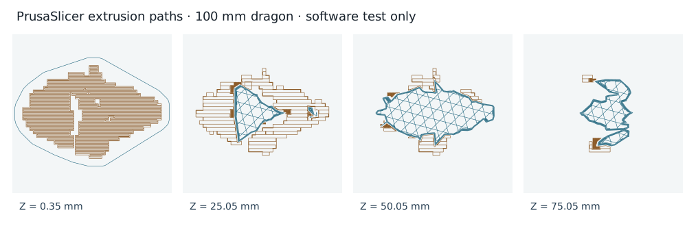
Import the STL using millimeters. Confirm the 100 mm height, inspect islands and overhangs, and review supports and bed adhesion. We used PrusaSlicer 2.9.6 with a generic test profile: 0.2 mm layers, 15% infill, supports enabled, a three-layer raft and a 5 mm brim. These settings are evidence of a software check, not recommendations for every printer.
The supported test slice completed: 516 layers, an estimated 6h 52m 29s, and 30,607.04 mm of filament. These are slicer estimates, not measured printer time or material consumption.
What this example proves — and what remains
The workflow checks whether a real GLB can become an STL with the intended size and pass a bounded slicer run. It does not establish physical print success, material strength, dimensional accuracy after printing, or suitability for a particular printer. We did not send the file to a printer.
If your own model has holes, intersecting surfaces or thin details, inspect and repair those separately. Our Blender workflow explains the import and cleanup handoff. Use the free viewer to inspect a file, or Studio to create a new starting model.